RZ11 iCon Processor
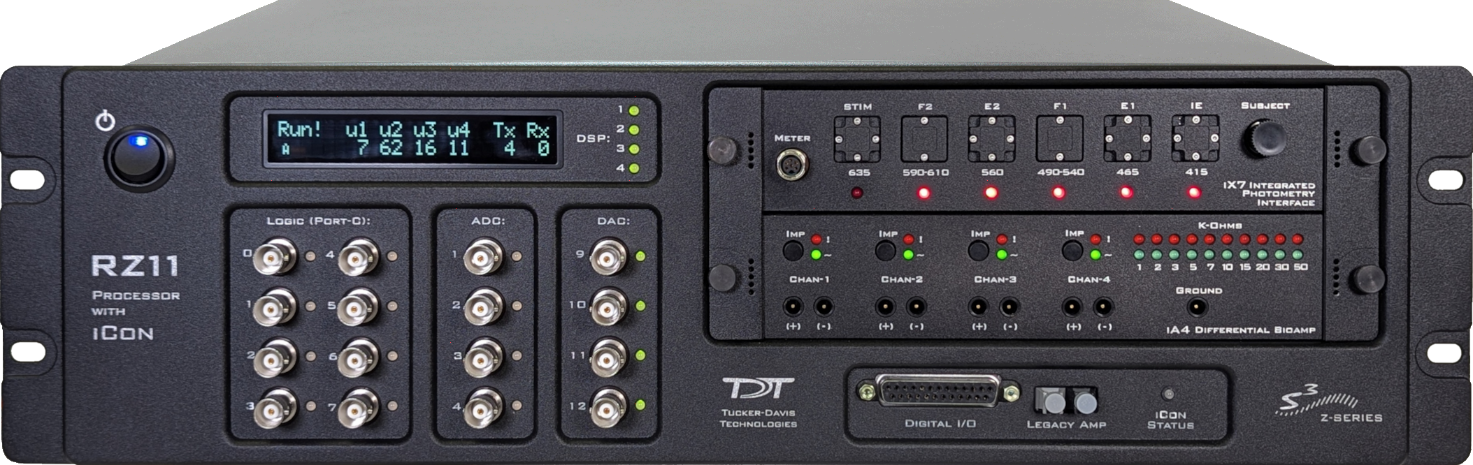
RZ11 Overview
The RZ11 iCon Processor supports up to four digital signal processor cards. Any card can be either a single standard processor card (RZDSP) or a quad core processor card (QZDSP). Standard single processor cards use a single Sharc DSP; quad-core processor cards use four Sharc DSP cores with the potential to more than double the power of the RZ11.
The RZ11 also features a built-in iCon2 for up to two iCon modules. See iCon Platform for more information on the iCon and the available modules. It has an additional eight channels of analog I/O (four input, four output), 24 bits of digital I/O, and an onboard fiber optic link for Medusa4Z amplifier, all available on the front panel.
Power and Communication
The RZ11's Optibit optical interface connects to a PO5, PO5e, PO5c, or UZ3 computer interface card for fast and reliable data transfer from the RZ11 to the PC. Connectors on the back panel are color coded for correct wiring.
The RZ11's integrated power supply is shipped from TDT configured for the end user's regional voltage setting (110 V or 220 V). If you need to change the voltage setting:
-
Turn off the RZ11
-
Use a small flathead screwdriver to gently push the clip along the left side of the fuse plate to the right to remove it.

-
Remove the white AC voltage selector and rotate it until the desired voltage is displayed, then reinsert it and put the fuse plate back on.
The RZ11 is UL compliant; see the RZ5 Operator's Manual for power and safety information.
Software Control
TDT's Synapse software controls the RZ11 and provides users a high level interface for device configuration.
RZ11 Features
DSP Status Lights
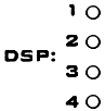
These LEDs report the status of the multiprocessor's individual DSPs and will be lit solid green when the corresponding DSP is installed and running. The corresponding LED will be lit dim green if the cycle usage on a DSP is 0%. If the demands on a DSP exceed 99% of its capacity on any given cycle, the corresponding LED will flash red (~1 time per second). For QZDSPs, the LED indicates levels for the core with the highest cycle usage.
Front Panel Display Screen
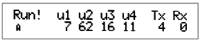
The front panel display screen reports detailed information about the status of the system. The top line reports the system mode, Run!, Idle, or Reset. The second line reports the DSP cycle usage. For QZDSPs, the highest core cycle usage is shown. The Tx / Rx show the percentage of sending / receiving data transfer capacity used.
Note
When burning new microcode or if the firmware on the RZ is blank, the display screen will report a cycle usage of 99% and the processor status lights will flash red.
Legacy Amp Port
The RZ11 is equipped with an amplifier input for direct connection to Medusa Preamplifiers. Physiological signals are digitized on the preamplifier and transferred across noiseless fiber optics. The Legacy Amp port can be used with any of the Medusa preamplifiers and is configured in Synapse software.
Onboard Analog I/O
The RZ11 is equipped with four channels of 16-bit PCM D/A and four channels of 16-bit PCM A/D. All 8 channels can be accessed via front panel BNCs marked ADC and DAC.
The following table provides a quick overview of the analog I/O features and how they must be accessed during experiment design.
Digital I/O
The digital I/O ports include 24 bits of programmable I/O. The digital I/O is divided into three bytes (A, B, and C) as described in the chart below. All digital I/O lines are accessed via the 25-pin connector on the front of the RZ11 and bits 0 - 7 of byte C are available through BNC connectors on the front panel labeled Digital. See RZ11 Technical Specifications for the DB25 pinout.
The digital I/O is configured in the Synapse RZn Hal.
The data direction for the Digital I/O is also configured in the Synapse RZn Hal.
The RZ digital I/O ports have different voltage outputs and logic thresholds depending on the type. Below is a table listing the different voltage outputs and thresholds for both types.
LED Indicators
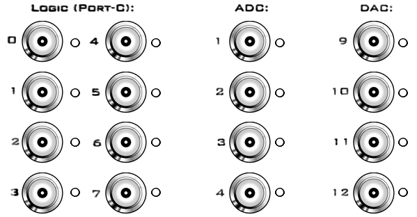
The RZ11 has 16 LED indicators for the analog and digital I/O located next to each BNC connector below the display screen.
Digital I/O
These LEDs indicate the state of the 8 bit-addressable I/O of byte C.
Analog I/O
These LEDs indicate the state of the four ADC and four DAC channels.
iCon Status Light
The iCon Status front panel display light reports the system connection information for the iCon2 built into the RZ11.
UDP Ethernet Interface
The RZ UDP Ethernet interface can transfer low bandwidth data directly to or from a PC. RZ devices equipped with a UDP interface have an additional Ethernet port and RS232 serial port located on the back panel. See RZ-UDP Communications Interface for more information.
Specialized DSP/Optical Interface Boards
The RZ standard DSP boards can be replaced with specialized DSP boards which include an optical interface for communication and control of RZ compatible devices, such as the Subject Interface and RS3 Data Streamer. RZ devices equipped with one or more specialized DSP boards include an optical port for each card. The ports are located on the back panel and labeled for easy identification.
* indicates a deprecated DSP: S was replaced with R, V is replaced with iCon iV2, P is a subset of M functionality, QZDSP_OPT is no longer supported
RZ11 Technical Specifications
Note
Specifications for amplifier A/D converters are found under the preamplifier's technical specifications.
Note
Technical specifications for preamplifier A/D converters are found in the specific preamplifier / stimulator document.
BNC Channel Mapping
Please note channel numbering begins at the top left block of BNCs for both analog and digital I/O and is printed on the face of the device to minimize miswiring.
DB25 Digital I/O Pinout

If using a PP24 Patch Panel, see PP24 to RZ11 Digital I/O.